
Quick Jetting Guide for Mikuni and Keihin CV
(carburetors with movable jet needles)
The following tips and insights are for your information only. These will not make you an expert tuner. We recommend that if you are a novice, you consult a professional mechanic or technician for your specific needs. The author cannot be responsible for your interpretation and usage of this information.
- IDLE: Set idle speed to proper r.p.m. by adjusting the IDLE SPEED SCREW. Turn the AIR SCREW to achieve the highest speed and best response. After adjustment has been made reset the IDLE SPEED SCREW to the proper r.p.m.
- OFF IDLE to 1/4 THROTTLE: The SLOW JET and AIR SCREW are most effective in this range When you want a richer mixture use a larger SLOW JET or turn the AIR SCREW in. The opposite holds true for a leaner mixture
- 1/4 to 3/4 THROTTLE: The JET NEEDLE is the most effective component in this range. Raising the needle by lowering the chip position at the top of the needle will richen the mixture. Lowering the needle will lean the mixture.
- WIDE OPEN THROTTLE: Changing the MAIN JET affects this range. Select the size which offers the best wide open throttle. performance, then install one size larger MAIN JET for ideal engine durability.
JETTING RANGE EFFECTIVENESS CHART
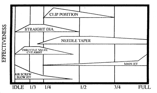
THROTTLE OPENING
Jetting Your Carb Circuits
To visualize how the various circuits overlap, please refer to the jetting chart. Always remember to change one carburetor component at a time and keep a record of your changes.
ZERO THROTTLE OPERATION (IDLE CIRCUIT)
IDLE SCREW:
Depending on your type of riding, adjust the minimum idle speed to desired RPM making sure the engine is up to operating temperature. If you do not desire any idle, make sure you turn in the adjusting screw just enough so the engine will not idle. This is especially important on Keihin PJ Series carbs in that the idle adjust knob (#4 in illustration) cannot be completely closed. Such an adjustment will result in a sluggish response off idle.
AIR/FUEL ADJUSTMENT SCREW:
The carburetor pictured in the exploded view uses an air adjustment screw (#5 in illustration) that is located "upstream" of the throttle valve (slide) and meters air. Turning the air screw counter-clockwise leans the mixture off idle. Some carburetors have this screw located "downstream" of the throttle valve, in which case, the screw meters fuel and opening the screw (counter-clockwise) results in a richer mixture. The idle screw usually has a range of one to two turns out from fully closed. If you need to adjust above or below this range, then the fuel jet will probably need to be replaced with a richer/leaner jet as required. Consult your owner's manual for the standard setting.
1/8 TO 1/4 THROTTLE
SLOW JET AND THROTTLE VALVE CUTAWAY:
Note - keep in mind that the idle adjust screw (air/fuel screw) gives a good indication of a properly sized slow jet (#6 in illustration). The slow jet calibrates the mixture from both the idle bypass and the idle orifice in the jet block. If the idle screw is properly adjusted, but the engine does not have good response when the throttle is wicked open, it is usually a sign of a lean mixture and the slow jet will need to be replaced with one size larger (richer) and the air/fuel screw re-adjusted. Consequently, if the throttle is only partially opened, such as in a trailing throttle situation, and the bike tends to load up, emitting a deep tone when the throttle is returned to full open, it is usually a sign of a rich slow jet. If the slow jet does not clean up this part of the circuit, the slide can be substituted for one with a different cutaway. The higher the number, the larger the cutaway will be, allowing more air to the jet block/nozzle screen leaning the mixture and, conversely, a smaller cutaway will richen the mixture with a greater effect up to 1/4 throttle.
1/4 TO 3/4 THROTTLE
JET NEEDLE:
The jet needle (#2 in illustration) is comprised of five major elements.
- Straight diameter section - In Keihin carburetors, either the last two digits or last letter denotes the diameter of the needle. The higher the last two digits, the leaner the needle and the lower the letter, the richer the needle. By going to a thinner needle, there is a larger area between the jet needle and the needle jet supplying a richer mixture.
- Length of the straight section - This determines at which point the needle taper will start relative to the clip position. If you have to run a needle in the highest clip position, a needle with a longer straight section should be used.
- Needle Clip Position - This works in conjunction with the length of the straight section. If the engine is too rich above 1/4 throttle, raising the needle clip (#1 in illustration) will lean the mixture.
- Needle Taper - A larger taper will result in a leaner mixture in the first half of the taper and a richer mixture in the last half of the needle. For example, a 1.34 taper will be richer in the first half and leaner in the second half of the taper than a 1.45 taper needle.
- Number of tapers - The needle can have one or more tapers; the number of tapers is not usually changed.
NEEDLE JET: The needle jet/nozzle controls the fuel/air mixture up to 3/4 throttle. How it overlaps with the jet needle depends on the jet orifice inner diameter, air bleed holes and type of nozzle screen. Most modern Japanese carburetors use a fixed needle jet/nozzle assembly which cannot be removed. It your carburetor has a removable needle jet/nozzle, please contact the manufacturer in order to decipher the nozzle code. It is advisable not to calculate how rich/lean the needle jet is by using exclusively the nozzle inside diameter to needle outside diameter discharge area.
WIDE OPEN THROTTLE
MAIN JET: The best track side method to determine the size of the main jet (#7 in illustration) is to fully load the engine on a long straightaway or hill. At the end of the stretch, chop the throttle and hit the kill button simultaneously. Now pull the spark plug. The parts of the plug you should be looking at are the positive electrode and last 1/4 of the ceramic insulator. Best power will usually result in a very light tan colored insulator tip and dark colored ring around the tip of the electrode. The electrode itself should have fairly sharp edges. For example, if the ceramic insulator has a nice tan coloring but the electrode has a white ring around the tip and the plug is of the correct heat range, then you can easily run a size larger on the main jet.
| Please keep in mind that the different brands of gasoline can give different readings. Also, race gas or aviation gas is more prone to oxidation and storage deterioration.. |
When jetting your main jet, try to remember to jet for the best power in a specific situation. As you gain experience and knowledge, you will be able to use other methods to determine your jetting. A good tuner can "feel" most of the circuits by slowly reving a parked bike, or just by looking at the color of the unpainted pipe and silencer.
Copyright © 1997 FMF Racing USA. All Rights Reserved
